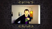
By routine reading of Photo-News and blogs from around the world, I came across homemade photo booths again and again. I saved images and ideas for my own project "somewhere in the future". Future was supposed to be 2012, when I moved to Hamburg and a housewarming party was planned. Unfortunately, that did not work out with the schedule, the project has been somewhat forgotten and thus lay for a while semi-finished in the basement. 2015, a colleague celebrated his birthday on a larger scale and they have established a selfie-booth. The result was great and reminded me of the photo booth in the basement, which was finally completed.
Like always I joint all the best ideas from other projects that I had found in the meantime.
These include:
- using a DSLR
- LED lighting or regular flash
- countdown timer
- WiFi for live viewing of images on screens or projectors
- web slideshow to ensure that only requires a browser on the client side. Ken Burns Effect FTW!
- rapid construction of themes for the slideshow
- classic look that can be used from birthday to weddings
- built-in photo filters for various occasions
- open source software as a basis

The result is the Photo Booth WiFi with built in Arduino to control lighting, countdown and shooting and with an extra Raspberry Pi, on which the filters are applied and the slideshow can be retrieved from.
Hardware
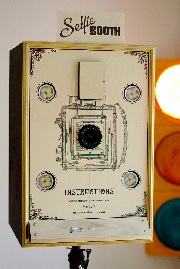
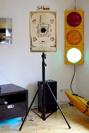
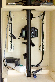
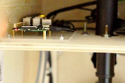
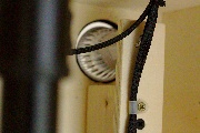
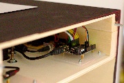
As housing a homemade wooden box made from 10mm plywood with dimensions of 40cm x 60cm x 36cm is used. It contains a second floor, in which a 35mm pole socket for tripod attachment is mounted. Also, here are the Arduino, Raspberry Pi and the control boards mounted. All body parts are glued, only the front panel is screwed down. The back wall is secured with four wing nuts. The case was painted on the outside with black tinting paint.
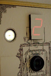
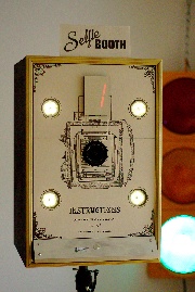
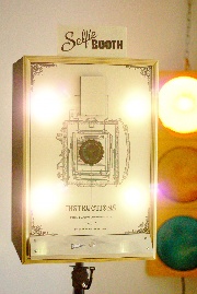
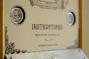
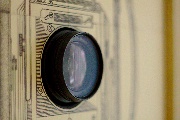
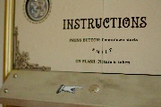
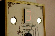
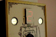
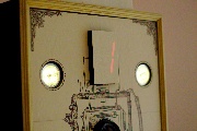
The front panel contains four cutouts (55mm) for the four LED lights (12V, 4W), a section (70mm) for the camera lens and holes for mounting and cable entry for the 7-segment display and the "panel" with the start button. As a "frame" a decorative strip of wood was used and had been painted with golden color. On the inside of the front panel mounting rails for the LED lighting are attached.
The camera mount is realized at the time temporarily with a cheap, modified tripod. The stand is to be replaced by a Manfrotto Magic Arm and Super Clamp.
Design and weathering
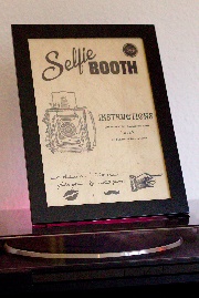
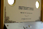
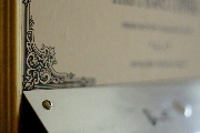
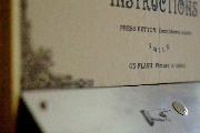
The whole assembly is held externally in the style of an old camera aka "vintage". The design of the front panel is formed from a mixture of finished and self-created elements. Great influence had various Photobooth projects that I've seen over the years. In the end I was using Inkscape to design a vector graphic, printed that one out on thick paper and cut it to size. To get the old, faded impression, the prints were placed for several hours in tea (Assam!) and then dried slowly over several days. The same procedure was applied for the two signs.
Electronics
The electronics of the Photo Booth WiFi mainly consist of two components: an Arduino to read the button state and to control the lighting, 7-segment display and camera combined with a Raspberry Pi, on which image processing is done (scaling and applying filter effects). Also clients can connect via WiFi to display the slideshow.
Camera control I: First, a control of the camera was planned via a USB connection with gphoto2 by the Raspberry Pi. This worked in principle, however, separate control of focus and shutter function by software was not supported for the camera I used (Canon EOS 1000D). Thus, it was not possible to focus the camera in low light, to then take the picture with a short flash of the LED lights. The entire process - focusing, image capture, download the photos (--capture-image-and-download at gphoto2) - takes about 6.9 seconds. During this time the software could not be determined how far the camera was so that the lighting had to be switched to maximum brightness all the time. This was unacceptable to me, because it is not very intuitive for the user (tested at a party). Another solution was found and more hardware was installed! (Note: newer Canon cameras support the separate control of the focus function by gphoto2, thus eliminating the expansion of hardware.)
Camera Control II: The Arduino now triggers focus and shutter separately. This is done through the normal remote port of the camera with 2.5mm jack. To (camera) security Arduino and camera are isolated by two optocouplers (4N35). This has the (unplanned) advantage that faster image sequences are possible, while the Raspberry Pi is busy with image processing.
The control of the remaining components is actually quite simple: the button is provided with a pull-up resistor and connected directly to the Arduino. The 12V LED lamps are controlled by a Darlington Array (ULN2003A) from the Arduino. Unfortunately, the 7-segment display has a common cathode (hence probably the cheap price ...), which did not make a control possible with an initially incorrectly installed ULN2803A. Luckily a "pin compatible" UDN2981A was at hand. Since all connections are realized via pin headers and Dupont connectors, the new connection was a breeze.
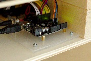
All components are mounted on an acrylic plate, which can be fastened with four screws in the housing. Thus, a repair or replacement of components is quite simple. The cables that run in the bottom of the box (LED lighting, 7-segment display, button), are led through cable hoses.
Programming
It was originally planned that the control of all components is performed by the Raspberry Pi. Since it is rather busy during image processing (scaling and applying a filter can take up to 20 seconds per image) and not particularly quickly responded to clients in the WiFi on the retrieval of images and since recently also the control of EOS 1000D did not work as planned, the complete control of the camera and the lighting was left to the Arduino.
The program execution on the Arduino is quite simple: after pressing the button, the four LED lights are turned on with low brightness (SoftPWM Library), the focus feature of the camera is triggered and the countdown starts on the 7-segment display. After 3 seconds, the countdown reaches zero and the lights are switched for half a second to a higher luminosity. At the same time the shutter of the camera is operated from the Arduino. After that, all lights are turned off and the Arduino shares via the serial interface with the Raspberry Pi that a new photo waits on the camera.
Note to the camera setting: The focus is set to AI Servo, so that the camera refocuses when there in movement. Exposure compensation is set to -1 to -1.5 stops to compensate for the brighter LEDs during exposure.
On the Raspberry Pi a wild mix of python, bash and php scripts is used to respond to new images, to initiate the processing and deliver the processed images to all clients. In order: a python script communicates with the Arduino and receives the notification of new pictures on the camera. Gphoto2 downloads the images from the camera and then they are saved to a flash drive (faster extraction, separation from the system). A php script keeps track of the images received and of processed images (scaled provided with effect filters) and processed all new images. The actual image processing is done by imagemagick (convert).
The Raspberry Pi runs in WiFi Access Point mode (hostapd) so that you can connect wireless-enabled devices with the Photo Booth. All browser inquiries are forwarded to the slideshow on the Raspberry using dnsmasq and Apache Rewrite. The slideshow is mainly composed of javascript to check for new images and some CSS3 for the typical Ken Burns effect (panning and zooming). When there are new pictures on the Raspberry, they are classified as next in the slideshow. With no new images, the existing images are displayed in random order. The design of the slideshow can also be stored on the USB memory stick so that it can be easily adapted and changed.
There is still the possibility to control the individual functions of the Arduino via the USB connector for maximum compatibility. So another camera could, as originally planned, be controlled by the Raspberry Pi. The Arduino is then only used to control the LED lighting and the 7-segment display and for reading the pushbutton. Running the whole unit without the Raspberry Pi is also possible, unless it is desired that the images are displayed directly as a slideshow. If not, they will instead remain on the camera.
TL;DR
Raspberry Pi + Arduino in a wooden box to control a camera and LED lighting. Including WiFi and displaying the images live on client side.
Links
